This is the schematic design to follow when trying to connect the Arduino Uno, the MPR121 breakout board and the modified shock gum toy.

There is also a push button included which is used to reset the LEDs when you have run out of lives. Pins 3 – 10 are used connected to the cathode of the LED and the anode is connected to a 220 Ohm resistor which is then connected to Ground. Pin 11 is used for the push button which is used as an INPUT so the function digitalRead will be used with it.
Also, as you can see the shocker has 3 ouput wires, two of the wires have to be connected to each other so that essentially you have two wires which will generate the shock. In the image below, the blue wire (OUTPUT A0, A1, A2) is connected to the pink wire. The brown wire is the standalone output wire. If both sets of output wires are touching each other, the shock will not work. Finally, the green wire is the Ground wire.
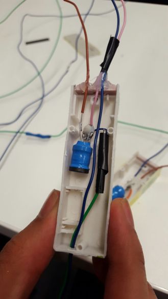
Shock Gum – Rewired
